Refrigerator Thermistor Is Not Reading Any Resistance
Fundamental Points
- Thermistors provide critical temperature information to the main control board which in turn governs the refrigerator operation
- Learn how to visually inspect, perform tests and if necessary supercede faulty thermistors temperature sensors
- All thermistors used in GE refrigerators are identical with office #WR55X10025. You can check the latest cost here
- Plan on testing/replacing the defrost thermostat at the same time
TIP
Although this department every bit intended for a GE Profile PFCF1NFW refrigerator, many information will be applicable to other GE refrigerators made after later 2006.
Table of Contents
- Background Info
- Thermistor Purpose and Location
- Visual Inspection
- How to Test a Thermistor
- Primal Takeaways
Groundwork Info
A thermistor, which is combination of the words thermal and resistor, is a blazon of resistor used to measure temperature changes and deliver differing electrical resistance in response to that alter. Because thermistors are highly sensitive in society to maintain temperature for refrigerators, it is vital to ensure that thermistors are working correctly 24/7.
Please note that at that place are two types of thermistors:
- Positive Temperature Coefficient (PTC) – resistance value increases every bit the temperature increases
- Negative Temperature Coefficient (NTC) – resistance value decreases as the temperature increases (i.e. inversely proportional)
Thermistors used in GE refrigerators are made upward of NTC (sintered metal oxides ceramic made of manganese, nickel, cobalt and other elements), combined with binders and stabilizers then pressed into a precise shape to dictate their resistance and temperature curve.
The master command lath provides an excitation voltage (+5v) to the thermistor with a ii-wire connectedness (this is because the thermistor change in resistance is large compared to the resistance of the leads).
The excitation is then converted to a voltage signal past the thermistor and the primary command board converts the measured voltage to temperature.
| Temperature (Fahrenheit) | Temperature (Celsius) | Resistance (Kilo-Ohms) |
|---|---|---|
| -twoscore | -twoscore | 166.eight |
| -31 | -35 | 120.five |
| -22 | -30 | 88 |
| -13 | -25 | 65 |
| -iv | -20 | 48.4 |
| 5 | -xv | 36.4 |
| 14 | -10 | 27.6 |
| 23 | -5 | 21 |
| 32 | 0 | 16.three |
| 41 | 5 | 12.7 |
| fifty | 10 | 10 |
| 59 | 15 | vii.8 |
| 68 | 20 | 6.2 |
| 77 | 25 | 5 |
| 86 | 30 | iv |
| 95 | 35 | iii.2 |
| 104 | 40 | 2.half-dozen |
| 113 | 45 | 2.ii |
| 122 | fifty | 1.eight |
| 131 | 55 | 1.5 |
| 140 | 60 | i.2 |
On the other hand, defrost thermostat is a less technologically advanced device consisting of bi-metals (oft fabricated of copper and aluminum) to open up or close its circuit based on temperature changes.
Keystone (Thermometrics) vs EPCOS Thermistors
Effectually 2010, GE discontinued using thermistors made by Keystone/Thermometrics under the General Electric Information Services (GEIS) characterization due to loftier failure rate caused by moisture penetration. Keystone/Thermometrics thermistors have an open bottom (commonly in black) at the betoken of wire entry into the polymer casing. This casing will also have a distinct "dome".
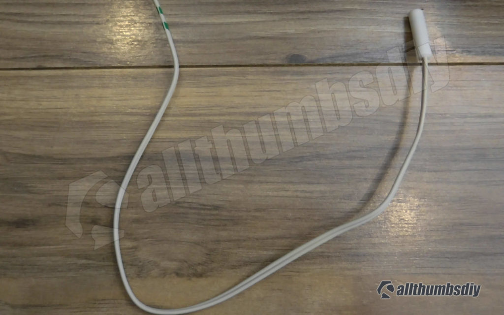
Since then, all GE refrigerators (not only PFCF1NFW model) contain EPCOS thermistors which have conductors embedded in a sealed, flat-top design in white polymer shells.
Regardless of a particular design, any colour discoloration, cracking or bulging would indicate a problem with the thermistor and it volition need to be replaced.
Iif you happen to find Keystone/Thermometrics thermistors, programme on replacing with the EPCO thermistors equally a precaution. All GE refrigerators use EPCOS thermistors (part number #WR55X10025)
^ Dorsum to Top
Thermistor Location
There are four thermistors located in a GE Profile PFCF1NFW refrigerator:
- Fresh food thermistor – located in the fresh food compartment (upper left wall, covered with a fish make full encompass plate). It provides temperature information in the "fridge" or fresh food (ff) compartment to the master command board that will determine if a damper should be opened or closed to increase/subtract cold air flow into the FF compartment
- Freezer thermistor – located in the FZ compartment (right wall, covered with a fish fill cover plate), it provides temperature data for the freezer (fz) compartment. This data is used to either ramp upward or slow down the compressor and/or condenser fan. The main command lath can also elect to shutdown the compressor and/or condenser merely continue to operate the variable speed evaporator fan.
- Ambient thermistor – located behind the toe kick plate (bottom of the refrigerator), it provides "ambient" or kitchen (or garage) room temperature (not inside of a refrigerator). This information is used in conjunction with FF and FZ thermistors to calculate the cooling requirement. If the ambient thermistor is not functioning properly, the main control board volition default and presume the ambient temperature is xc F and will Not make whatsoever aligning to the fresh food or freezer set indicate.
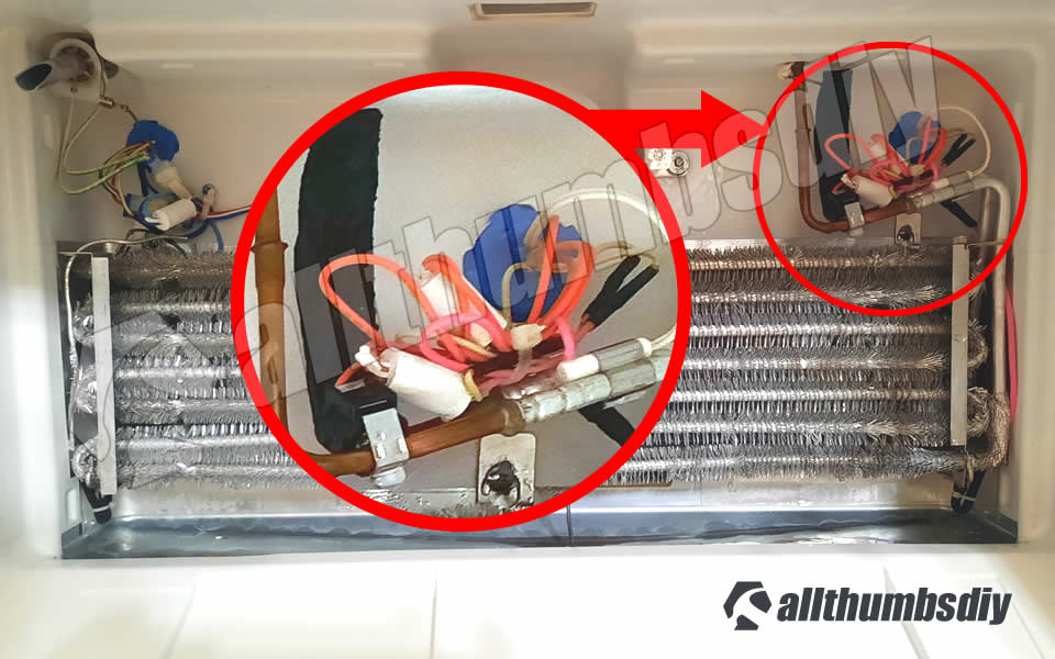
- Evaporator thermistor – located in the freezer compartment clipped on to the suction tube of the evaporator. This particular thermistor acts as the chief detector (defrost temperature sensor acts as a backup) to see if defrosting wheel needs to exist turned on
^ Back to Top
Defrost Thermostat Location
Defrost thermostat is located in the freezer compartment, usually clipped tightly on to a tubing attached to the evaporator.
In many cases, a defrost thermostat is found next to the evaporator thermistor and to gain access, you lot will demand to remove many parts out of the fashion (door, shelves, panels).
Thermistor/Defrost Thermostat Failure Symptoms
Here are some obvious symptoms of a declining thermistor:
- Fridge also warm / freezer common cold
- Refrigerator / Freezer too warm
- Defrosting cycle does not work (i.due east. ice build upwardly on the evaporator)
- Displayed temperature is not accurate
- Excessive cooling outside set parameter
- Erratic/fluctuating temperatures throughout the 24-hour interval
^ Back to Top
What Causes Thermistors to Fail
Thermistors rarely, if e'er, fail completely (which would make our task very easy), although we sometimes see a thermistor fail due to an open up circuit resulting from a break in wires between the thermistor and primary control board. This usually happens when wires are spliced incorrectly allowing wet penetration.
The virtually common reason why thermistors fail is simply crumbling. Over fourth dimension, sintered not-oxides in thermistors lose its efficiency and provides signals that are no longer accurate.
^ Back to Top
Tin can You Tell a Failing Thermistor Past Visual Inspection?
Obvious color discoloration, cracking or bulging would be great to quickly solve a malfunctioning refrigerator but unfortunately, virtually failures involve internal chemic degradation in resistance over a catamenia of time. That means you CANNOT rely simply on a visual inspection to detect your problem.
Instead, yous should TEST each thermistors using a multimeter (see adjacent section).
^ Dorsum to Top
Using Self -Diagnostics to Examination for the Thermistors?
Not if you value your time.
Y'all certainly tin can run the self-diagnostics but this examination tin only detect a closed or open circuit and thermistors normally do not fail this style. Instead, sintered non-oxides in thermistors lose its potency and lose their ability to provide correct resistance.
^ Back to Top
How To Test a Thermistor
You will need a multimeter to perform these tests. If you need one, read my post How to buy a Multimeter article.
Please remember that thermistors are a VDC component so a shorted thermistor will shut downward the entire fridge.
Information technology can likewise deviate from their normal value or resistance at any given temperature, resulting in "too warm" or "roo cold" complaints.
There are three ways to test a thermistor:
- Not-subversive, Passive testing from the chief control board (ohm meter part)
- Advantages – quick / minimal amount of piece of work
- Disadvantages – cannot test thermistor located on the evaporator suction tube
- Not-destructive, Active testing from the main control board (voltage meter function)
- Advantages – quick / minimal corporeality of piece of work
- Disadvantages – cannot examination thermistor located on the evaporator suction tube
- Destructive testing from each location
- Advantages – evaporator thermistor can exist tested in a controlled environment
- Disadvantages – requires cut and re-splicing wires
Destructive testing method requires cut off thermistors, exam them and re-installing them back into original place. Removing thermistors make it piece of cake to test (especially for the evaporator thermistor that is in a very tight space), BUT splicing wires back volition be hard because existing wires are very curt.
Thus we volition only review the non-destructive (active and passive) testing method in this post.
TIP: Evaporator Thermistor and Defrost Temperature Sensor
Unless the evaporator thermistor and defrost temperature sensor have been replaced recently, I highly recommend skipping the test for these two sensors and just replace both of them.
^ Back to Top
Non-destructive Testing
For this method, you volition be testing the resistance from the opposite end of a thermistor that terminates at the chief control lath. Passive testing method volition just measure the resistance; agile testing method will measure the excitation voltage (more accurate) across a thermistor.
Please note that both leads from the multimeter will be touching the wires from the sensors. Some other words, multimeter test leads should Not be touching the pins on the main control lath.
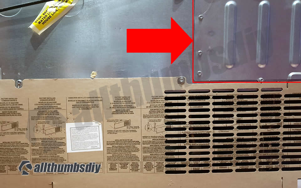
- Footstep # i – pull out the refrigerator to proceeds access to the rear panel
- Step # 2 – using 3/viii″ socket, remove screws from the cover to expose the principal command lath
- Footstep # 3 – Touch any part of the rear metallic panel (only not almost the main control board) to belch static electricity from your body
- Step # iv – Multi-meter comes with reddish and black test leads; since we are not testing for polarity, information technology does not matter which atomic number 82 goes to terminals
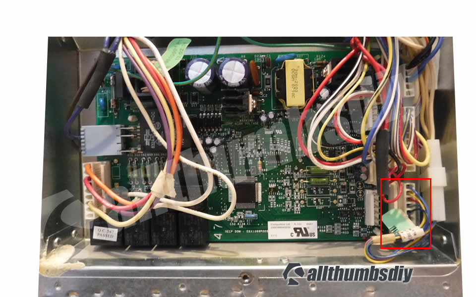
- Pace # five – There are v pins at the J1 jumper on the main command lath
- Pin 1 – Fresh Nutrient Thermistor (blue wire)
- Pin 2 – Ambient Thermistor (yellow wire)
- Pin 3 – Freezer Thermistor (scarlet wire)
- Pin 4 – Evaporator Thermistor (green wire)
- Pin 5 – Thermistor Voltage Supply (+5 VDC)

^ Dorsum to Acme
Passive Testing Method
You will need to unplug the fridge before starting this examination. Set your multi-meter to ohm.
Test the Fresh food (FF) Thermistor
- Step # 6 – Remove the FF thermistor fish gill comprehend (located on the upper left wall in the fridge compartment and gently pull out the thermistor
- Step # seven – Submerge the thermistor in a small zip-loc bag and duct tape to the wall with ice and a pocket-sized corporeality of water for 5 minutes (will approximately simulate 32 degrees in Fahrenheit)
- Footstep # 8 – Remove the wire retention wire harness clip at the primary control lath
- Step # ix – Insert the red lead from a multimeter into the pivot ane on the retention wire harness prune (not the main control board)
- Footstep # ten – Insert the black atomic number 82 from a multimeter into the pin 5 on the retention wire harness clip (not the primary command board)
- Step # xi – Take an OHM reading from your multimeter; information technology should be around 16.iii Kilo-Ohms (sixteen,300 Ohms). Whatsoever reading that is more than or less than v% from this value means your thermistor is bad and will need to exist replaced.
^ Back to Top
Test the Freezer (FZ) Thermistor
- Stride # 6 – Remove the FZ thermistor fish gill cover (located on the right wall in the freezer compartment) and gently pull out the thermistor
- Step # 7 – Submerge the thermistor in a pocket-size glass (or small zippo-loc handbag and duct tape on the wall) with ice and pocket-sized amount of h2o for 5 minutes (will approximately simulate 32 degrees in Fahrenheit)
- Footstep # 8 – Remove the wire retention wire harness clip
- Footstep # viii – Insert the blood-red lead from a multimeter into the pin 3 on the retention wire harness clip (not the main control board)
- Stride # nine – Insert the blackness pb from a multimeter into the pin 5 on the retention wire harness clip (not the main control board)
- Step # 10 – Take an OHM reading from your multimeter; it should be around xvi.three Kilo-Ohms (16,300 Ohms). Any reading that is more or less than 5% from this value ways your thermistor is bad and will need to be replaced.
^ Back to Superlative
Test the Ambient Thermistor
- Step # six – Remove 2 screws holding down the toe kick panel, put aside the panel; cutting off the naught necktie holding downwards the thermistor
- Footstep # 7 – Submerge the thermistor in a modest zip-loc handbag with ice and small amount of water for 5 minutes (will approximately simulate 32 degrees in Fahrenheit)
- Step # 8 – Remove the wire retentivity wire harness clip
- Pace # 8 – Insert the red lead from a multimeter into the pin 2 on the retention wire harness prune (non the principal control board)
- Step # ix – Insert the black lead from a multimeter into the pivot v on the retention wire harness prune (not the principal control board)
- Step # 10 – Have an OHM reading from your multimeter; it should be around sixteen.3 Kilo-Ohms (16,300 Ohms). Whatever reading that is more or less than v% from this value means your thermistor is bad and will need to be replaced.
^ Back to Top
Active Testing Method
Yous volition need to exit your refrigerator plugged in for this test to measure voltage drop beyond thermistors.
WARNING
Please be careful as you can easily damage the principal control board by accidentally touching other parts!
Set your multimeter to voltage meter.
Test the Fresh nutrient (FF) Thermistor
- Step # 6 – Remove the FF thermistor fish gill embrace (located on the upper left wall in the fridge compartment and gently pull out the thermistor
- Stride # 7 – Submerge the thermistor in a small zip-loc bag and duct tape to the wall with ice and a small-scale amount of water for v minutes (will approximately simulate 32 degrees in Fahrenheit)
- Pace # viii – Remove the wire retention wire harness prune at the master command board
- Step # ix – Insert the blood-red lead from a multimeter into the pin 1 on the retentivity wire harness clip (not the master control lath)
- Step # 10 – Insert the black pb from a multimeter into the pin five post on the primary control lath
- Step # xi – Have a voltage drop reading from your multimeter:
- 0 VDC = defective; circuit shorted out; replace
- 0-i VDC = possibly defective; replace
- ane to 4 DC volts = acceptable
- 4-v VDC = peradventure defective; supercede
- >5 VDC = open circuit (i.e. infinite resistance); supervene upon
^ Back to Top
Test the Freezer (FZ) Thermistor
- Pace # 6 – Remove the FZ thermistor fish gill cover (located on the right wall in the freezer compartment) and gently pull out the thermistor
- Pace # 7 – Submerge the thermistor in a small glass (or small zip-loc handbag and duct tape on the wall) with ice and small amount of water for 5 minutes (will approximately simulate 32 degrees in Fahrenheit)
- Step # 8 – Remove the wire retention wire harness prune
- Step # 9 – Insert the red lead from a multimeter into the pin 3 on the memory wire harness prune (not the primary control board)
- Step # 10 – Insert the black lead from a multimeter into the pin v on the main control board
- Step # 11 – Take a voltage drop reading from your multimeter:
- 0 VDC = defective; circuit shorted out; replace
- 0-1 VDC = maybe defective; replace
- 1 to iv DC volts = adequate
- 4-5 VDC = possibly defective; supplant
- >5 VDC = open circuit (i.e. infinite resistance); replace
^ Dorsum to Top
Exam the Ambient Thermistor
- Stride # 6 – Remove 2 screws belongings downward the toe kicking panel, put aside the panel; cutting off the zip necktie belongings down the thermistor
- Step # 7 – Submerge the thermistor in a small zip-loc purse with water ice and small amount of water for 5 minutes (volition approximately simulate 32 degrees in Fahrenheit)
- Stride # 8 – Remove the wire retention wire harness clip
- Step # nine – Insert the red lead from a multimeter into the pivot 2 on the memory wire harness clip (not the main control lath)
- Step # x – Insert the black pb from a multimeter into the pivot v on the master control board
- Step # 11 – Accept a voltage drop reading from your multimeter:
- 0 VDC = defective; excursion shorted out; supervene upon
- 0-1 VDC = possibly defective; supercede
- 1 to 4 DC volts = acceptable
- 4-5 VDC = possibly defective; replace
- >5 VDC = open circuit (i.east. space resistance); supervene upon
^ Back to Tiptop
Test the Evaporator Thermistor (a.k.a. defrost sensor)
- Evaporator thermistor is bundled together with other wires, tucked into the upper right hand corner behind the evaporator comprehend
- Considering it is in a tight bars space and lots of parts need to be removed to proceeds admission, I highly recommend that you skip the test and get right to replacing both the evaporator thermistor and defrost heater thermostat at the aforementioned fourth dimension (unless they accept recently been replaced)
Test the Defrost thermostat
Defrost thermostat in GE refrigerators are secondary back upwards to thermistors so they rarely neglect.
If your refrigerator is not cooling properly, I would supervene upon it (costs under $twenty) along with the evaporator thermistor . Please refer to the diagram # 266 in my parts page for the latest office # and toll.
^ Back to Top
How to Supervene upon a Thermistor or Defrost Thermostat
Should y'all demand to supplant a thermistor, use plastic bell connector (part # WR01X10466) to splice the wires and fill each connector with RTC102 silicone to prevent h2o penetration.

^ Back to Meridian
Cardinal Takeaways
It can be very stressful and confusing to troubleshoot a non-working fridge, especially with many automated features like digital temperature maintenance and auto-defrost.
However, most problems can be solved if y'all triage the problem and each components.
Adept luck with your project!

Commonly Asked Questions
What happens when a defrost thermostat goes bad?
This defrost termination thermostat (Defrost Limiter Thermostat, High Limit Thermostat, Fridge Defrost Bi-Metal Thermostat) acts as a safety device to stop the evaporator curlicue from overheating, by turning off the defrost heater at the end of the defrost bicycle. This part attaches to the tubing of the evaporator coil in the freezer. A faulty defrost termination thermostat may issue in the defrost heater never heating and a solid frost buildup on the evaporator roll, which results in likewise warm temperatures. The thermostat contacts are normally closed and have continuity until it reaches 140 degrees. If this high limit thermostat is open up at room temperature or colder, it is lacking. This limit thermostat has an attached mounting clip and comes with pink and amber wire leads. The thermostat is one inch in bore and ane/ii inch thick, the 2 wire leads are ten inches long.
REFERENCE LINKS
- Thermistors (external link, Wikipedia)
- Thermistors and NTC Thermistors (external link, electronics-tutorials.ws)
- Temperature Sensors (external link, electronics-tutorials.ws)
- Troubleshooting Thermistor Problems in refrigerators (external link, YouTube-Sears Parts Direct)
- Sintered Metal Oxide for Thermistor (external link, US Patents-Google)
talbotbleanto1999.blogspot.com
Source: https://allthumbsdiy.com/appliances/how-to-test-and-replace-thermistor-temperature-sensors
Post a Comment for "Refrigerator Thermistor Is Not Reading Any Resistance"